1
Usage1) Diagnosis Program
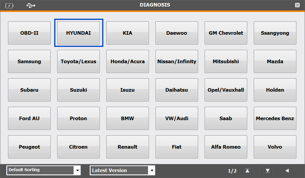
Entry into Diagnosis Mode : Manufacturer -> Model -> Equipment(Ex. Hyundai)
- Entry into Maker Selection Screen
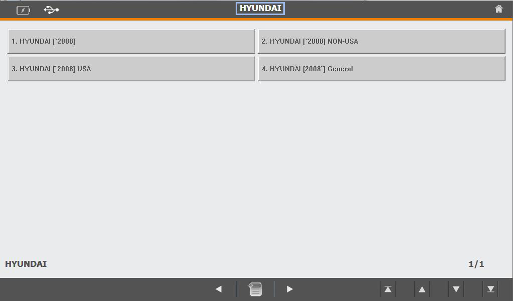
- Entry into Maker Bottom Menu
- Entry into Model Selection Menu
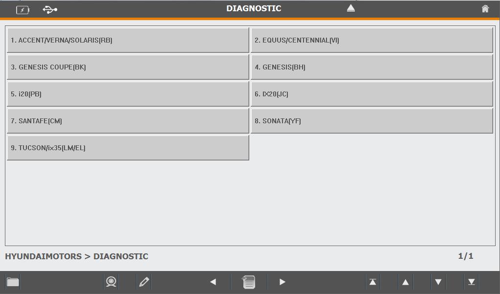
- List of Diagnosis
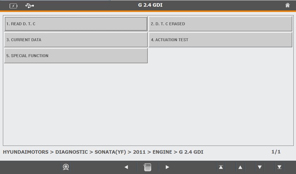
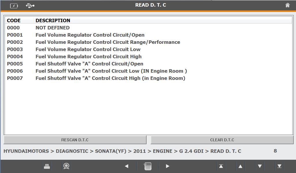
① Self Diagnosis
- Read/Removal of Trouble Code
- In case of [i]mark is showing at the front of CODE, For the relevant
Trouble Code Sensor shall be support by “ Help” by double click
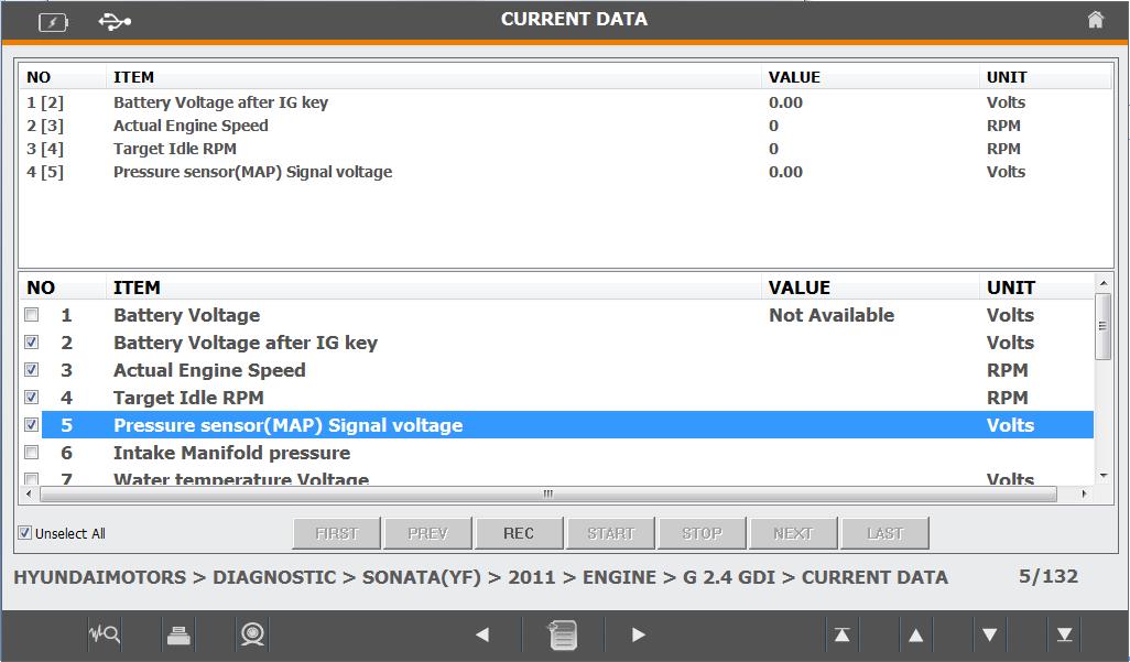
② Service Data
- Indication of Real time Data/Graph for the Sensor
- Graph Indication Button and Recording Button shall be activated,
Selected List is able to be executed the function of indication
for Recording and Graph.
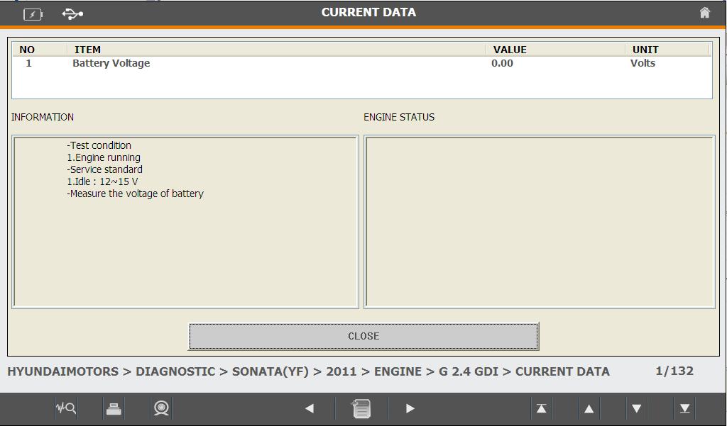
- In case of [i]mark is showing at the front of CODE, For the relevant
Trouble Code Sensor shall be support by “ Help” through double click
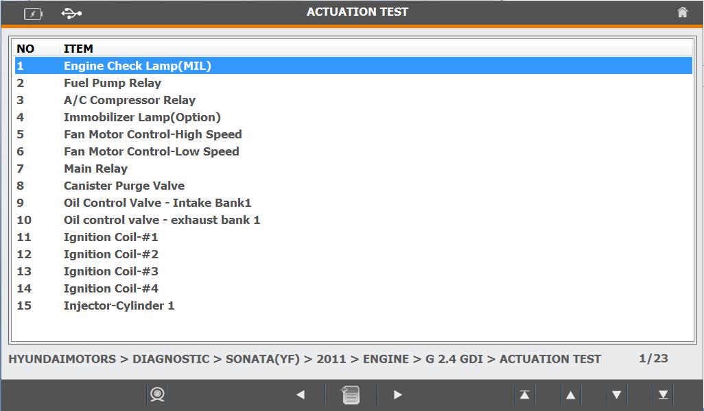
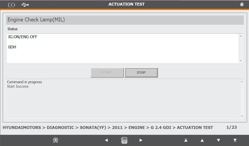
③ Random Operation(Compulsion Drive/Special Function)
- According to Use Environment, Relevant Menu is not able
to be supported
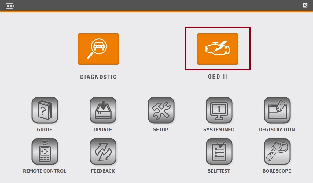
2) Program of OBD-II
Entry into OBD-II Mode after selection of OBD-II
- Entry into OBD-II Communication Menu

- Entry after selection of “ GENERIC OBD2 “ Menu
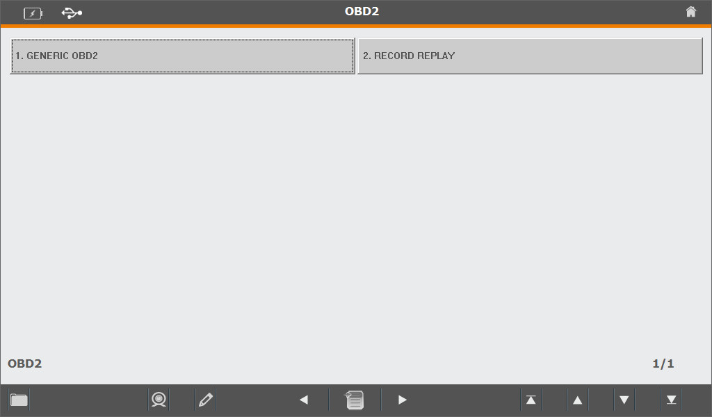
- If executed, Communication of vehicle to be diagnosed shall
be scanned automatically
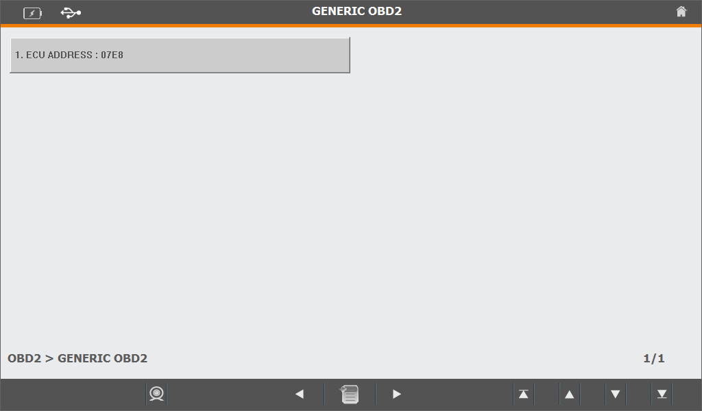
- If communication is successfully done with Vehicle, A Button with
Relevant ECU Address Information shall be generated
- Entry after selection of Relevant Button
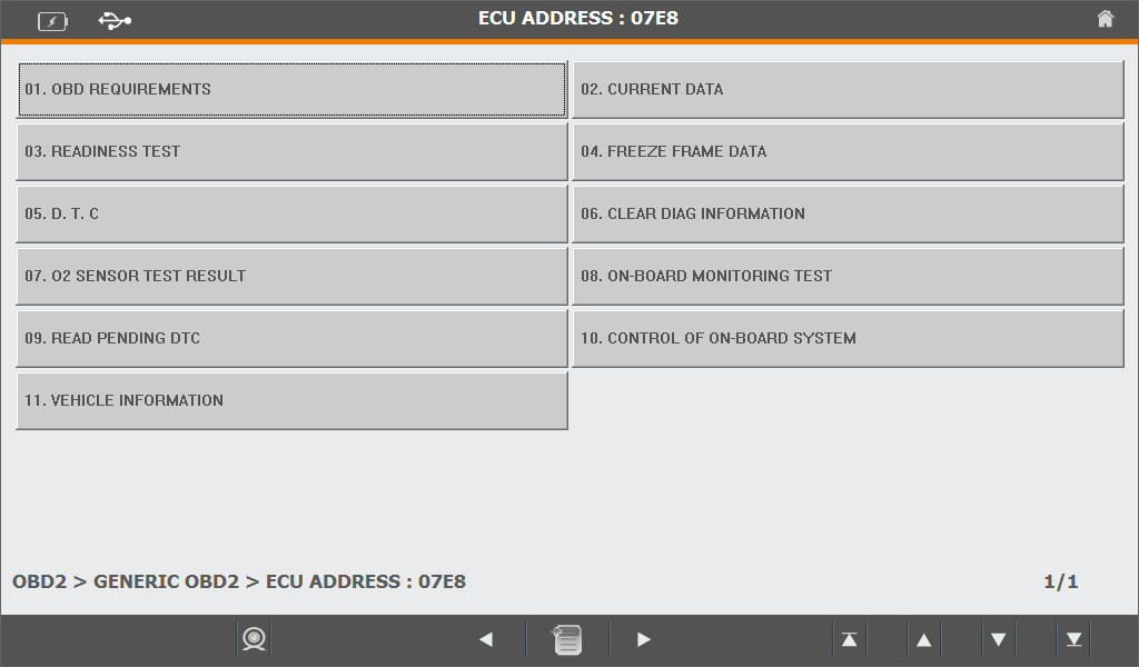
- Dignosis Button shall be shown if entry after selection of
Relevant Button
- 01. OBD REQUIREMENTS – Required type of OBD to be shown
- 02. CURRENT DATA – Diagnosis Data of Vehicle to be shown on
Real time.
- 03. READINESS TEST – Stand by Condition of Vehicle to be shown
- 04. FREEZE FRAME DATA – Fixation Frame Data of Vehicle to be shown
- 05. D.T.C – Trouble Code of Vehicle to be identified
- 06. CLEAR DIAG INFORMATION – Trouble Code of Vehicle to be
removed
- 07. O2 SENSOR TEST RESULT – Oxygen Sensor Monitoring Test of
Vehicle to be shown by result
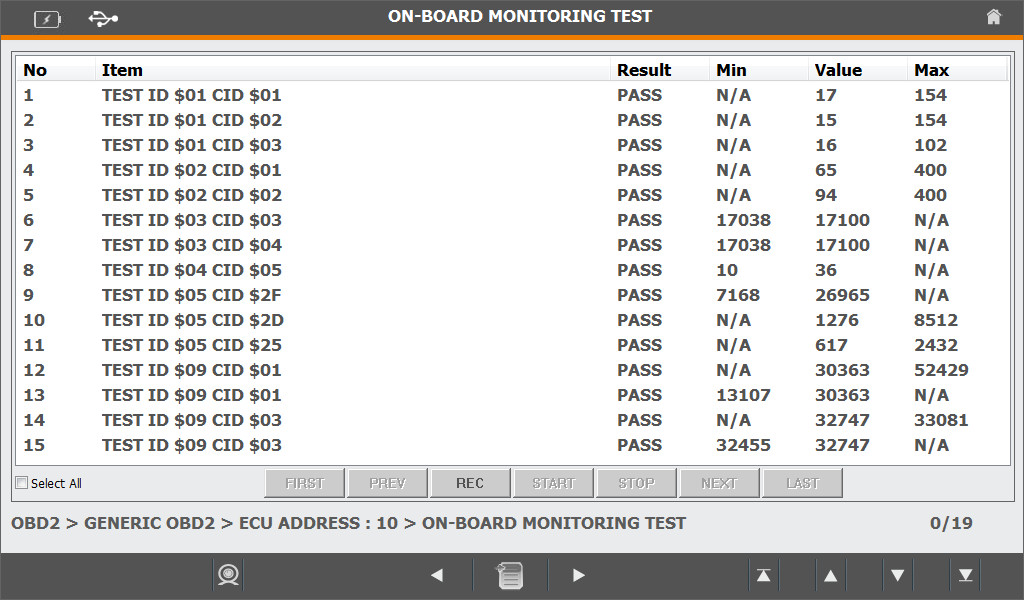
- 08. ON-BOAD MONITORING TEST – ON-BOARD Monitoring Result for
Specified Monitoring System of Vehicle to be identified
- 09. READ PENDING DTC – The Data to be revised as trouble code of
Vehicle to be shown
- 10. CONTROL OF ON-BOARD SYSTEM – ON BOARD System of Vehicle
To be tested and Requirement of Component to be controlledn
- 11. VEHICLE INFORMATION – Information of Vehicle to be identified
Indication of Menu for each Protocol : “ ON-BOARD MONITORING TEST” shall be differed visible menu according to protocol of vehicle
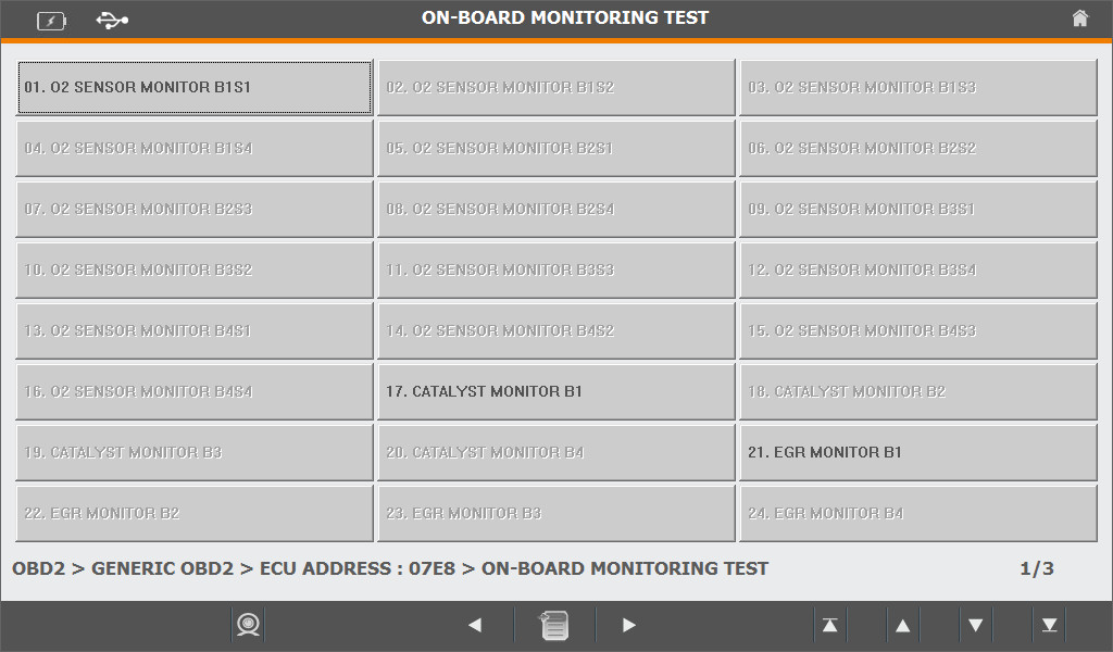
- In case of Vehicle to be used CAN Protocol
- In case of Vehicle not to be used CAN Protocol
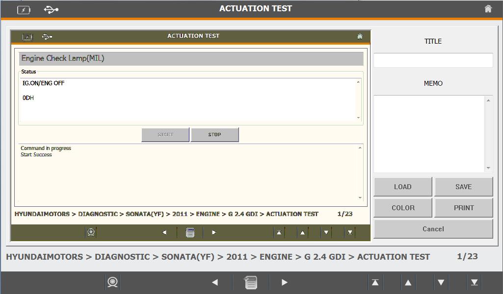
3) Optional Function of Diagnosis Program
① Screen Capture(Capturing for Screen of Diagnosis Program)
- Click the Icon of Screen Capture, Entry into Captured Screen
(Screen of Program shall be saved automatically during click on Icon
– ex, Screen of Random Operation)

- Click the Icon of COLOR, Color of Brush Pen to be selected
(Supporting for drawing of picture on Captured Screen by Mouse)
- Click the Icon of SAVE, Revised Captured File and information of
TITLE/MEMO to be saved
- Click the Icon of PRINT, Roaded Captured File to be printed
- Click the Icon of LOAD, Saved Screen to be loaded
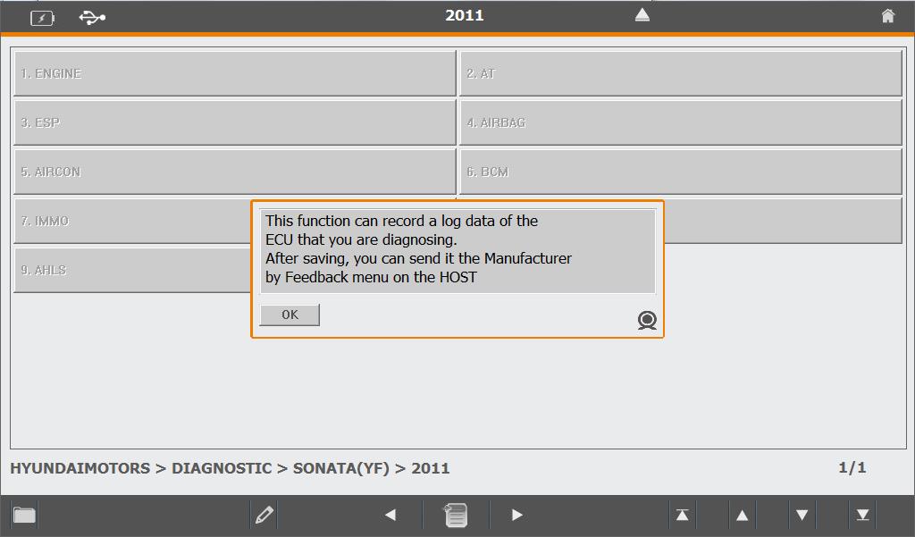
② Record of Log Data
- The function is saved the information to be sent Feedback if Trouble
caused during on scanning
- The Icon to be activated only for the case of Diagnostic if Scanner on
mode of execution
- Click the Icon of Record Log Data from Equipment Selection Menu
(Log Data Record mode ON – shall be identified Log Data saved or not
during on moment of escape from Equipment Selection Menu at the
Diagnosis List menu after scanned from later on)

- If Log Data Record Mode to be “OFF”, Icon shall be Clicked once again.
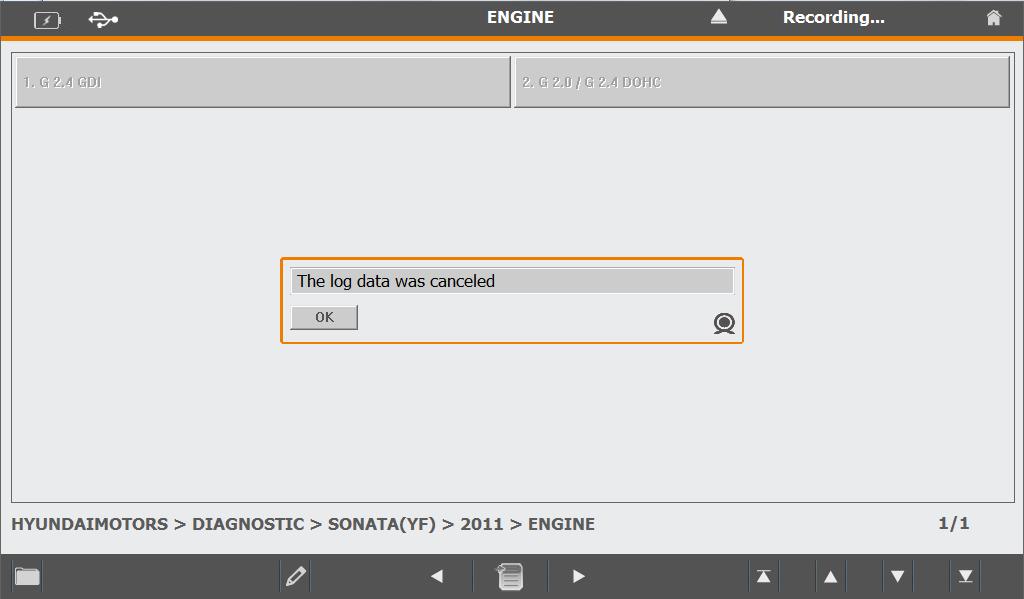
- Entry into Log Data Record Screen(Entry the moment of escape to
Equipment Menu from Diagnosis List)
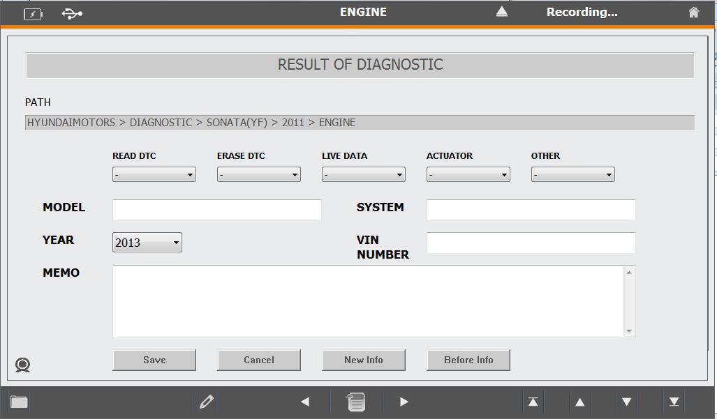
- Selection and Composition for Relevant Details Information of Error
(BEFORE INFO. Provided the information easy to be input after loading
of Previous Input Information if click the Icon)
- Saved after click on SAVE Icon

1) Preparation for Feedback Information
Preparation Procedure of Feedback Progress(Feedback Transfer is function to be transferred saved log data during on scanning)
- No.1 : Log Data Record Mode ON at the Diagnosis Program
(Clicked the Icon)
- No.2 : Escaped to Equipment Selection Menu after scanned of troubled
Equipment.(Log Data Record – Available for input of Optional
Information)
- No.3 : Repeated No.2 against Troubled Equipment
- No.4 : Log Data Record Mode OFF(Click the Icon)
(If Log Data Record Mode to be OFF, General Diagnosis to be used
continuously due to not be entered into Log Record Screen
after scanned.)
Transfer available by one-time during on internet after recording of Log Data for several maker.
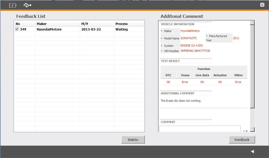
2) Procedure of Feedback
Entry into Feedback Screen(Using after connection through Internet)
- (Screen shall not to be shown due to not transferred Feedback during
on First Entry)
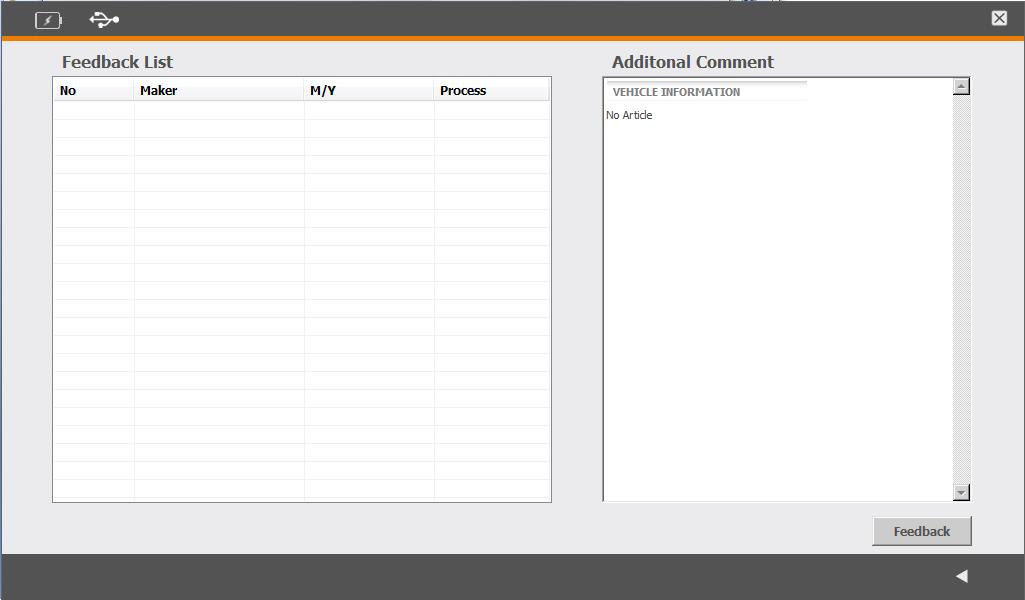
Feedback Transfer(Click the Feedback Button)
- Indicated the information for feedback of Maker, Date, Situation of
Disposal on the left side of Screen
- Indicated the information for Selected Feedback Information and
Response for feedback by Engineer on the right side of Screen.
- If Button of Delete to be clicked, Selected Feedback List from right side
of Screen View to be removed.